Intro:
Been playing around with NSX for a while now on more advanced scenarios than what was required for VCIX-VN and one of the very cool features is Cross-vCenter NSX on top of it being a requirement for couple of customers looking for workload mobility in Disaster Recovery scenarios. On top of Universal Security policies, the best feature about Cross-vCenter NSX is extending L2 VXLANS over any type of L3 WAN connection between HO and DR thus making Business Continuity plans that much easier in both active/passive and active/active scenarios. More so Enterprise features like Cross-vMotion or even vCenter enhanced linked mode are note a requirement for Cross-vCenter thus making standard licensing in DR more optimal and viable solution.
Unfortunately most guides out there including VMware Cross-vCenter NSX Installation Guide do not actually cover all required steps to get this working properly and honestly they shouldn’t since each network is different and requirements vary especially when Local-Egress is involved and different routing mechanisms are to be used. The best guide that comes close to giving a holistic view of requirements is VMware Disaster Recovery with NSX and SRM Guide but again some steps are very high level and a bit confusing if you haven’t dug deep into NSX.
That been said if no custom routing is required or Local-Egress is not to be used then the Cross-vCenter NSX implementation is straight forward but that is never the case and will never be. Every customer has different network setup/requirements on top of different DR plan for different workloads so that granularity is always required and thus I believe it would be great if a complete requirement is put forth and tackled in terms of step by step implementation even from the physical router/firewall perspective so that it can be used as a baseline for any custom requirements easily.
The aim of this is post is to specify each and every step required to get Cross-vCenter NSX working with/without Local-Egress, well its with both ways but how to get VMs to use HO as a route for all VMs even ones running in DR or get VMs to out the route that is local to their site meaning if a VM is hosted in DR it would go from the DR gateway and if a VM is hosted in HO it would go from the HO router and both of which communicate together and are hosted on the same VXLAN subnet. As discussed, all scenarios can be visualized so lets put forth the most required scenario out there and conquer it.
On a side note, VMware trying to sell professional services, seemed eager to state that this is something not handled easily by partners and they better be involved (not an official statement but is being projected to customers). Well we are not just going to actually handle it from A to Z but also release it to the public community in the hope that this kind of misconception is put to rest.
Scenario:
I have the luxury of operating two physical labs ( Big Thanks to Diyar ![]() ) that are totally independent so for this guide NO workarounds at all, this is the real thing being implemented and tested on two environments over VPN with 8MB bandwidth so its as real as it gets in production environments so fear not incase virtual networks,routers,nested hypervisors complicate things in your mind or give the perception this is just a test lab.
) that are totally independent so for this guide NO workarounds at all, this is the real thing being implemented and tested on two environments over VPN with 8MB bandwidth so its as real as it gets in production environments so fear not incase virtual networks,routers,nested hypervisors complicate things in your mind or give the perception this is just a test lab.
I want to achieve the following with this scenario:
-
VMs in HO and DR using same logical universal network VXLAN can communicate with each other.
-
VMs in HO and DR using same logical universal router and different logical universal network VXLANs can communicate with each other.
-
VMs in HO and DR use the internet router in HO so VMs in DR communicate with internet through the router/public IP in HO.
-
VMs in HO and DR use different internet routers to communicate with the internet so VMs in HO use the HO router/public IP and DR VMs use the DR router/public IP to reach the internet.
-
VMs in HO and DR on logical switches VXLANs can communicate with the physical network VLANs in HO and DR.
HO consists of two VMware vSphere 6.5 hosts running on Cisco UCS and DR consists of one VxRail appliance holding four VMware vSphere 6.5 hosts both of which have their own dedicated vCenter with embedded PSC and different SSO domain so they are not linked in any way, shape, or form.
Every site has a Cisco Catalyst 4500 10GB switch connected to all servers in the site and to a MikroTik Router acting as an internet gateway. Both sites are connected using MikroTik IPSEC L3 VPN tunnel over the internet so that is my WAN connection (Obviously MPLS is a better option but for a lab its actually a dream come true).
NSX 6.3 Manager is deployed in each site and connected to its respective vCenter server and that’s about all the configuration I will take for granted in this post knowing that you can find many resources on how to get that configured.
OSPF is going to be used to distribute routes between Universal DLR and ESG in each site. Static routes are going to be used for enabling access to physical environment (VLANS) which would be using the UDLR thus L3 (different than bridging ports between VXLAN and VLAN which would be L2) and to be used for giving VXLANs internet access in terms of reverse route from the physical router back to the ESG then to the UDLR.
Local-Egress will be utilized on UDLR to control routing traffic flow for VMs in HO and DR. How this works is routes are advertised by the UCC to the clusters based on the Locale ID set on this clusters. If Cluster in HO and in DR have the locale ID the same as the UDLR in HO this means that both will have the same routes and use the ESG in HO. If HO cluster is assigned the Locale ID of UDLR in HO and DR cluster in assigned the Locale ID of UDLR in DR this means that VMs hosted in HO will use the ESG in HO and VMs hosted in DR will use the ESG in DR while at the same time both being on the same network/subnet.

Scope:
-
Change Cisco 10GB ports MTU to 1600 on catalyst (Nexus switch different command just google it) and make sure vDS is also set to 1600 MTU in HO & DR.
-
Set NSX Manager in HO as primary and add NSX Manager in DR as Secondary.
-
Add NSX Universal Controller, Prepare clusters/hosts in both sites, and configure logical network preparation (VXLAN, Segment ID, Universal Transport Zone) in HO & DR.
-
Create Universal Logical Switches (One for Transit network from UDLR to ESG in HO, One for Transit network from UDLR to ESG in DR, and your internal networks as many as they are as I will use only one for testing called “VXLAN” for the sake of simplicity).
-
Create UDLR from Primary NSX Manager in HO (Local-Egress) and configuring required interfaces, IPs, Gateway, Routing, OSPF, and Locale Egress ID.
-
Add appliance to UDLR in Secondary NSX Manager in DR and configuring required required interfaces, IPs, Gateway, Routing, OSPF, and Locale Egress ID.
-
Create ESG in HO and DR with required interfaces, IPs, Gateway, Routing, and OSPF.
-
Set Locale-ID for Egress traffic based on the required traffic on HO & DR Clusters.
-
Create Static route for logical switches on physical router for reverse internet traffic for each site & create static route on UDLR to access physical network in HO & DR from VXLAN VMs.
Test, Test, and Test ![]() .
.
Environment:
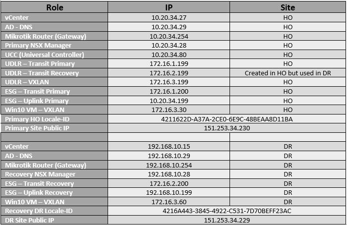
Configuration:
1- Telnet to Cisco Catalyst switch and run the following command on all ports connected to the ESXi hosts vDs (For Nexus switches follow the following guide from VMware “ design-guide-for-nsx-with-cisco-nexus-9000-and-ucs-white-paper.pdf “ for setting L3 and L2 MTU with Jumbo Frames):
switch# conf t
switch(config)# interface Tengigabitethernet 1/1
switch(config-if)# mtu 1600
switch(config-if)# end
switch# show interface Tengigabitethernet 1/1
switch# wr
switch# exit

Verify vDs MTU network settings set to 1600:

2- Set primary NSX manager in HO and add secondary NSX manager.
Go to Networking & Security / Installation / Management on HO vCenter and press on Actions to assign NSX Manager in HO as Primary Role.


After NSX manager is assigned primary role, click on Actions / Add Secondary NSX Manager and provide the IP or FQDN of the NSX Manager in DR with its username/password.


Login to vCenter in DR and make sure NSX Manager is assigned as secondary.

3- Create Universal Controller (By default controller created on the primary NSX Manager is considered a universal controller UCC and will be synced ), I will create one but it is recommended you create 3 at least. Go to Networking & Security / Installation / Management on HO vCenter and press on the green button under NSX Controller nodes. Specify all the information required, The connected to interface should be a PortGroup or virtual network connected to your physical environment which is accessible through the layer 3 WAN link from DR in our case VPN. IP Pool is a group of IP addresses reserved on the connected interface for assignment to the controllers so if you are adding 3 controllers you create a pool that has 3 free IP addresses from the PortGroup that is connected to the UCC from your physical network (exclude from DHCP if you have one). Controllers are added one by one so wait until the first is deployed and start the second deployment and the same for third. This is only done in HO.


Go to Networking & Security / Installation / Host Preparation, press on Actions and Install. After that is completed press on Configure under VXLAN for the clusters. This needs to be done in HO and DR. VXLAN preparation installs VTEP on each server so it requires an IP address on each host in the cluster thus an IP Pool is required with free IPs corresponding to the number of servers in the cluster. The VXLAN interface should be the vDs connected to your physical network which is configured on the L3 IPSEC VPN WAN link. Also make sure the MTU is 1600 which should come by default and VMKNic Teaming Policy Fail Over.
One note here is that I couldn’t take a snapshot of my own VXLAN Configuration because its already completed and I would need to put every host in maintenance mode so took a snap from VMware documentation never the less for me its the same configuration but with NO VLAN as I only have one subnet on my physical network.


If any issue occurs and an error is shown on the installation phase or VXLAN phase just click on the configuration icon and press Resolve All.
Now go to Logical Network Preparation / VXLAN transport and make sure everything is ready and vmk IPs are green checked. Also make sure that the VXLAN port is the SAME in HO & DR.


Head over to Segment ID , Now Segment ID Pool should be different in HO & DR but the Universal Segment ID Pool should be the same (It would be synced from HO). Click on Edit in each site and set Segment ID Pool in HO to 6000-6999 and set Segment ID Pool is DR to 7000-7999. Set Universal Segment ID Pool in HO to 15000-16000 only on the primary NSX.


In HO Primary NSX Manager head over to Transport Zones click the green plus button to add a universal transport zone (you can add only one universal transport zone), Make sure to Select Mark this object for universal synchronization. Choose Unicast and select the HO cluster.

Go back to Installation / Management, press on Actions on top of NSX Manager, and choose Perform Universal Synchronization and press Yes.


In DR NSX Manager go to Installation / Logical Network Preparation / Transport Zones, right click the universal transport zone that should have appeared now after synchronization and make sure to connect the DR cluster.

4- In HO Primary NSX Manager go to Logical Switches and create the following:
-
Transit-Primary: This will be used to connect the UDLR in HO to Edge in HO.
-
Transit-Secondary: This will be used to connect the UDLR in DR to Edge in DR.
-
VXLAN: This is just a network I will use to test virtual machines, you would name it App, DB, Web, or any other name the makes sense and create a lot more
 for me just one is fine for now.
Make sure they are connected to the universal transport zone we created earlier. Note that Segment ID associated with each logical network is in range of the universal segment pool we created earlier 15000-16000.

Go back to Installation / Management, press on Actions on top of NSX Manager, and choose Perform Universal Synchronization and press Yes so that the logical switches are visible in DR site.
5- In HO Primary NSX Manager head to NSX Edges and click on the green plus button to start creating the UDLR with Local Egress:
Note the Universal Logical Router and Enable Local Egress … Press Next .

Make sure the password is complex and long enough

Choose on which cluster/host/datastore the UDLR VM will be deployed, Press Next.

Connect the HA interface configuration to your vDs PortGroup (The one trunked to your physical network) and assign an mgmt. IP but that is not mandatory so I wont.

Now we need to add the networks that this UDLR will route so for each logical network we created earlier, we are going to create the subnet and gateway for that network on the UDLR.
The VXLAN network and any other network you would like to create operate as your production VXLANs that VMs are going to use and the IP on this UDLR would be the gateway for those VMs. Note that the type is Internal, the Connected to is the logical VXLAN created earlier, and the configured Subnet IP is the gateway for this subnet and the subnet prefix is how big the subnet is. MTU 1500 is fine and if more logical networks are created than add the subnet here so that it is routable.

The Transit-Primary logical network is used to connect the UDLR instance VM in HO to the Edge Gateway that will be created in HO later. The subnet created here is only for connection between UDLR and ESG so it can be a /29 not /24 as couple of IPs are only required. Note the type is UPLINK, the connected to is Transit-Primary logical network, and the subnet can be anything (that you wont use later in production).

Because we want to use Local-Egress and have the flexibility of using either sites or one specific site as default gateway to our VXLAN network, The Transit-Recovery is used to connect the UDLR instance VM in DR (will be created soon) to the EDGE Gateway in DR so incase of full HO failure, the VMs in DR (existing or failed over using SRM or RecoverPoint for VMs) are not impacted and keep operating using the same logical network (IP & Gateway). Note the type is UPLINK, the connected to is Transit-Recovery logical network, and the subnet can be anything (that you wont use later in production).

The default gateway settings on the next screen is the IP on the Transit-Primary logical network added to the EDGE gateway in HO. For DR although it is the same UDLR but we will change the gateway to reflect a new IP on the Transit-Recovery subnet. We will do that when we create the DR instance for the UDLR. Note that the IP 172.16.1.200 will be configured on the EDGE in HO when created. In DR it would be 172.16.2.200 which represents the .2 subnet for Transit-Recovery.

Next and Finish. Give it some time to deploy the UDRL VM and get things deployed.

After Deployment on UDLR in HO is completed, it should like this, double click to check the interfaces configured earlier:


Great all seems to be going as planned , now go back to Installation / Management, press on Actions on top of NSX Manager, and choose Perform Universal Synchronization and press Yes so that the UDLR are visible in DR site.
6- Lets configure Routing for UDRL in HO Primary NSX Site:
Go to Networking & Security / NSX Managers / Click on the IP of the NSX Manager / Summary Page and copy the ID.

Go back to Networking & Security / NSX Edges and double click on the UDLR then head to Routing tab. Click on Edit under Routing Configuration and paste the ID copied earlier. Always Publish Changes after every change.

Make sure that the default gateway section is as configured earlier, Transit-Primary is the interface and the IP is 172.16.1.200 which will be configured on Edge.

Click on Edit beside the Dynamic Routing Configuration section on the same page and choose the Transit-Primary as the Router ID. This is required for OSPF. Make sure changes are published before going to other sections.

On the left go to OSPF section and click on edit under the OSPF Configuration, the protocol address in an IP on the same subnet that the Transit network in HO was created so give it a free IP from the same range I gave 172.16.1.198 and the forwarding address is the IP of the Transit network that was assigned to the UDLR itself in HO so its 172.16.1.199 .

Create a new area definition “ 2” .

Map the Transit-Primary to Area ID 2 and Publish Changes.

Go to Route Distribution and Enable OSPF.In the Redistribution table add OSPF and Allow learn from Connected. Publish changes and we are done with UDLR for now in HO so lets create the UDLR second appliance in DR with its respective routing configuration.

In DR go to Networking & Security / NSX Edges , double click on the UDLR and navigate to Manage / Settings / Configuration.
On the HA Interface Configuration click Change and choose a Distributed PortGroup.

Under Logical Router Appliances click the green add button and add a new appliance for this UDLR in DR.

Now we have one UDLR which was created in HO on the primary NSX and synched to DR. Inside this UDLR we created a new appliance in DR so its not a new UDLR but rather an appliance of the same UDLR created earlier. This is required incase a full disaster recovery scenario and HO is fully down and/or if specific VM workloads active in DR will go to the internet through the DR router. Notice that if we go to interfaces we cannot edit or add since this is a universal object and can only be managed from Primary NSX that is why we created the Transit-Recovery (which will connect this new UDLR VM in DR to the Edge in DR) from the Primary NSX Universal logical switch and universal DLR.

In DR go to Networking & Security / NSX Managers / double click the IP of the NSX Manager , Copy the ID.

Go back to NSX Edges and double click the UDLR. Go to Manage / Routing / Global Configuration , Edit the routing configuration and paste the ID. Also change the Default Gateway settings for the interface to point to Transit-Recovery and gateway to point to the DR ESG IP which we will create later on. In the dynamic routing configuration change the primary router ID to Transit-Recovery.


Go to OSPF and enable OSPF. Set the protocol address to 172.16.2.198 and the forwarding address to 172.16.2.199 . Notice both are on the Transit-Recovery subnet which is 2 because they are in DR. Create the Area “2” and Map the interface Transit-Recovery to that area.

Head to Route Redistribution and enable OSPF with Permit Connected Routes.

We are done with UDLR in HO & DR. Lets start with ESG in HO and DR as well.
7- NSX Edge Services gateway is not universal and is handled in each site independently. An ESG will be created in HO and another will be created in DR both of which connect to the same UDLR created earlier using the Transit-Primary and Transit-Recovery logical networks.
In HO head to NSX Edges and click the green plus button to add a new edge device.

Make sure password meets complexity requirements.

Add NSX Edge appliance and choose the cluster that the ESG VM will reside on.

Now we need to configure 2 interfaces. One internal that will connect to the Transit-Primary and One Uplink that will connect to the physical network router through a vDs PortGroup.


Default gateway would be the physical router gateway in our case the Mikrotik LAN IP on the Uplink-Primary interface just created earlier.

Configure Firewall default Policy and Accept/Enable.

Finis the Deployment and wait until status of ESG shows as deployed.

Double click on the ESG-Primary and go to the Routing tab. In global configuration make sure the gateway is as configured when creating the ESG and edit the the Dynamic Routing Configuration to point to Uplink-Primary interface.

Go to OSPF tab and enable OSPF, create area “2”, and map interface Transit-Primary to area “2”. That is it for HO Edge, lets head to DR afterwards.


Go to Route Redistribution tab, enable OSPF, and Enable distribution of Connected routes.

In DR head to NSX Edges and click the green plus button to add a new edge device. It is the same exact steps listed above but the interfaces and IPs are different. I will only show the required changes so follow the above steps and change what is listed here below in terms of configuration. I have called it ESG-Recovery.


8- Now we have to set the Locale ID for the clusters/hosts so that UCC knows which route to send to which cluster. I will set the Locale ID for HO cluster the same as we set for HO UDLR so all VXLAN VMs in HO will go out to the internet through the ESG in HO only. I will set the Locale ID for DR cluster the same as we set for DR UDLR so all VXLAN VMs in DR will go out to the internet through the ESG in DR Only. Later in testing I will show you how a VXLAN VM running in DR can use the ESG in HO to go to the internet and vice versa is applicable in the same manner.
In HO ( remember the ID we copied from NSX Primary Manager in HO earlier ) go to Networking & Security / Installation / Host Preparation, click on actions and press Change Locale ID. This will apply to the whole cluster but can also be done for a specific host if you press beside the host IP in the installations status tab on the small config drawing on the right.


In DR follow the same steps while putting the Locale ID that was copied from the DR NSX Secondary Manager:

9- In terms of internal routing, everything is handled by OSPF so nothing has to be added manually in either sites. In terms of external routing we need to do the following:
-
Add static routes on the physical routers in each site to direct VXLAN subnet traffic (and any logical network used for VMs) to the ESG uplink IP so that reverse traffic coming from the internet to those VXLAN subnets is able to reach its destination.
-
Add static route on the HO UDLR which directs traffic going to the physical network in DR through the HO Edge ( since the DR physical network is not broadcasted by OSPF we have to state traffic going to DR have to go through the HO ESG then through the L3 VPN WAN tunnel). Add static route on the DR UDLR which directs traffic going to the physical network in HO through the DR Edge.
On the HO router add the following route (the 172.16.3.0 is the VXLAN network that will host VMs, add all the VXLAN subnets that will host VMs so that they have internet connectivity) Note that it is pointing to the ESG uplink interface in HO:

On the DR router add the following route ( Note that the route is for the same VXLAN subnet in HO since its the same logical network but it is going to the ESG uplink IP in DR) :

In HO Primary NSX UDLR Static Routing settings add the following to have connectivity to physical network in DR:

In DR Secondary NSX UDLR Static Routing settings add the following to have connectivity to physical network in HO:

Testing
Lets test based on the desired outcome so that every scenario is covered and troubleshooting is easier.
1- VMs in HO and DR using same logical universal network VXLAN can communicate with each other.
A Windows 10 VM is created in HO and DR each connected to VXLAN logical switch. Both are assigned an IP within the 172.16.3.0/24 subnet with the gateway being the UDLR Transit-Primary IP in HO and Transit-Recovery in DR.
Win10 VM in HO : 172.16.3.30
Win10 VM in DR: 172.16.3.60


2- VMs in HO and DR use different internet routers to communicate with the internet so VMs in HO use the HO router/public IP and DR VMs use the DR router/public IP to reach the internet.
Win10 VM in HO connected VXLAN using the ESG in HO:

Win10 VM in DR connected VXLAN using the ESG in DR:

3- VMs in HO and DR use the internet router in HO so VMs in DR communicate with internet through the router/public IP in HO.
We need to change the Locale ID of the cluster in DR to point to the Locale ID of the Primary NSX Manager in HO so that internet traffic in DR is routed through ESG in HO.


4- VMs in HO and DR on logical switches VXLANs can communicate with the physical network VLANs in HO and DR.
VM in HO can communicate with local physical network and DR physical network:

VM in DR can communicate with local physical network and HO physical network:

Recommendations:
-
Configure HA for UDLR in HO and DR.
-
Configure HA for Edge and utilize ECMP.
-
For Ingress traffic control use IP Prefixes and Allow/Deny rules.
- Create a minimum of 3 universal controllers.
Conclusion:
I have tried my best not to make any assumptions or take any kind of configuration for granted so that the whole setup is clear and well documented. I realize this can be done in different ways and for different requirements but I have found out this setup to be the best way to go.
Love to hear your comments.
Salam ![]() .
.
Hi. Why pick Unicast over Multicast as the Universal Transport Zone replication? Is Unicast more desirable for cross-vc NSX?
Hi . Good question actually. For me I just didn’t want any dependency on my physical network because I invested in a very low end switch ( honestly a very small mikrotik router with embedded 4 ports ). Unicast does incur additional overhead especially in terms of CPU but it is still my preferred way for a 100% software defined solution with no dependency on hardware features what so ever . Technically if you have L2/L3 switches in both sites already setup, I see no reason why not to use Multicast , but if you can spare some CPU threads, I would go with Unicast.
Thanks! One other question. How does NSX handle routing from external sources. For example. An external user contacts one of your services running in Site A. The request ends up at Site B but the service vm is at Site A. NSX directs the packets over VXLAN to the vm at Site A. If local egress has been configured and NSX sends the packet out Site A (and out through it\’s edge firewall), will that break any sort of routing (symetric vs asymetric routing)?
To control ingress traffic you can utilize a route prefix list, subnets would be only advertised from the Protected site preventing the recovery site from receiving any inbound traffic or dynamic routing can be used to control the same. I would very much recommend reading the following document which covers your requested scenario “Disaster Recovery with NSX and SRM”. BTW as an update I would also use CDO mode to make sure the recovery procedure in DR is much fast since when a failure occurs all controllers in main site will be down so new hosts and or VMs would not be able to use any VXLANs. CDO is still in technical preview but I do recommend it for certain DR scenarios.
Thanks. It was more directed towards a question of how active/active datacentres configured with cross vCenter NSX would handle ingress – so IO initially goes to the appropriate site initially. Your answer seems that it relates to an active/passive type model (traditional SRM model).
Locale ID coupling with local ESG only works for initiated outbound traffic in Active/Active DC setup. For inbound in Active/Active DC, there would be traffic tromboning happen. Otherwise any stateful inspection would fail.
waow!! its what i am looking for!
Thanks for this great effort i really appreciate it, i have pretty much same setup for my lab. One quick question. what is the MTU at mikrotik end?
Thanks
MTU is 1600 because I am using it a switch as well. Thanks 🙂 .
Hi ,
I cannot edit universal logical switch and universal logical distributed router in secondary NSX manager site but I can only edit this object in the primary NSX manager site .
Please let me know how to solve this problem.Thank.
Hi, 100% True, that is default behavior, In the primary site you would add the logical switch that will be acting as uplink in your DR to ESG in DR and assign it an IP that you will use in DR between the DR UDLR and DR ESG. Same thing for the DLR, use the procedure in the post to create it in the DR site. “Notice that if we go to interfaces we cannot edit or add since this is a universal object and can only be managed from Primary NSX that is why we created the Transit-Recovery (which will connect this new UDLR VM in DR to the Edge in DR) from the Primary NSX Universal logical switch and universal DLR.”
In post, I am using Transit-Recovery LS which was created in primary site even though it will be used in secondary/DR site. The ESG in DR will be connected to the UDLR in DR (the second UDLR appliance we added in DR” using the Transit-Recovery LS. I hope that makes sense or else drop me an email using the Contact button and we can check your configuration.
Hi,Thank for your explanation and so how to put local ID for DR site we need to put local ID in DR but I can’t add loacal ID in DR and then I also tried to put loacal ID of DR in DC site .And that also not fine.
Please let me know how to put local ID of DR site .Thank again.
Hi, you change it at the cluster level , go to Installation, Host preperation , Right click Cluster and set the Local ID to the Local ID of the primary or secondary NSX manager site depending on how you want routing to be configured. You can find the local ID of each site in NSX Manager in summary settings which is also depicted in post above.
The UDLR in each site should have the same Local ID as the local NSX Manager so the primary UDLR has the same Local ID as the primary NSX Manager and DR UDLR has the same Local ID as NSX Manager in DR and you can edit Local ID for UDLR in both primary and secondary sites in the routing tab of UDLR settings.
Go back in post and follow the steps carefully it should be enough else let me know so that we can check it together.
Thanks.
I will check that with your suggestion on Monday.
Please let me know what happen if I will create UDLR with vkernal mode , not virtual appliance mode .
UDLD mode is prefer which mode appliance mode or vkernal mode.
Thank.
When you create UDLR, don\’t forget apply egress option.
Nice…Just a trivial question that I always miss…What is exactly required from a configuration point of view on the switches in between the two sites?
Nothing special from NSX perspective in regards to switches configurations except for the 1600 minimum MTU. Thanks.
Thanks for the detailed representation. How did you ensure end to end MTU size of 1600? Wouldn’t this end to end MTU be required to run an active active data center where we’ve extended the UDLS? Did you have to communicate with your service providers at each end to provide you with an MTU of 1600 end to end? This is the part i’m confused on 🙂
Thanks again for the outlay. Great work!
It depends if your WAN connection is L2 or L3 . In this setup it is an L3 IPSEC Site to Site WAN connection so I have full control on both ends of the connection never the less if its a L2 connection through a service provider then yes you have to communicate with them for the same since any network carrying VXLAN traffic has to have a minimum MTU of 1600 . Hope it helps. Thanks.
Thanks again for your response. Perhaps I’m missing something. Is your L3 IPSEC site to site over public circuits or a leased/private connection? As i understand it, even as an L3 IPSEC, the VXLAN headers are added to the packet creating larger than 1500 packet size meaning this could only be run on a circuit where you can communicate with the provider to set the approp MTU? Apologies if i’m speaking in circles 🙁
100% True, any kind of WAN connection would require a minimum 1600 MTU , what I meant was with an IPSEC tunnel I have control of both routers so I cant set MTU/MSS to 1600 never the less in a L2 , VPLS lets assume connection type , you wont have control over all the devices between both ends so you have to make sure that the provider is aware of your required MTU config. I hope that makes sense.
🙂
It makes sense, but still confused on how you got MTU 1600 guaranteed end to end. Here is my visualization. Two Sites, Router A is at site A Router B is at Site B.
At Site A you set your router MTU to 1600. Router A connects to the public Internet via Provider A. Your IPSEC packets to router B have to traverse Provider A’s network and whoever Provider A peers with to get to Provider B where your 2nd router is connected.
Looking at the example above of Provider A’s packet traversal, how is MTU of 1600 guaranteed across Provider A’s network before it reaches Provider B’s network and your router connected to provider B?
I guess I’m wondering for this to work, did you have to talk with the provider to honor your MTU of 1600 end to end?
Thanks again for your prompt responses. Much appreciated.
I get your confusion 🙂 no worries , because my traffic is encapsulated inside an IPSEC tunnel it cannot be manipulated or changed by provider so whatever settings I set will be delivered as is . Other types of L2 or L3 links might be setup by your provider which normally deliver a pre-configured router without giving access to end user so this is where you should make sure you relay your requirements so that they configure it accordingly.
From his reply, I think he didn’t get your question.
From my experience, the provider can only guarantee end to end 1600 MTU if they manage ALL the infrastructure, meaning Privider X manages the router in site A and also the one in site B.
If you have different providers in each site, I don’t think they can honour 1600 MTU all the way.
Hi thanks for this great post.can we achieve this 100% with nested Esxi ?
yes I see no reason why not, use a virtual router (Freesco or VyOS ..) to simulate WAN connection and 2 environments located on different subnets connected through the virtual router. Thanks.
we have a enhanced linked mode Vcenter environment. My goal is deploying Cross Vcenter NSX for Universal Distributed Firewall only. I now that Controller cluster is not required for this scenario. But my concern is Transport zone. For the NSX Manager sync i need to create transport zone with segment id. All in all i stucked in this part cause i never deployed Cross Vcenter NSX. Could you give me a clue. Which steps needs to be done. Thank you very much
thanks for your case study it’s been helpful so much to me, but I’ve the same scenario as you but using dynamic routing OSPF in the core layer and eBGP between the ESGs and TOR. in both site.
how can i provide active/active in my scenario and control the ingress traffic ?
as i see, the ingress control should be at the core layer device using route map or at the ToR, i don’t think it will be at the ESGs.
can you give me a hand in this scenario if you understand what i mean, and if you have any related documents please can you share it regarding this scenario.
thanks 🙂
Hi
Does your MikroTik Router also run ospf area 111 with edge and UDRL?
Thanks.
Yes but I went with Static not to complicate the setup. You can run OSPF or BGP .
Hi, thanks for your great sharing, I did exactly like you did, it worked just fine except the comm between vxlan vms, i.e: 172.16.3.30 cannot ping 172.16.3.60, what couls possibly went wrong? Please enlighten me, thanks in advance..
If you could email me the response, would be fantastic and grateful..
Dear Sir , The Demo of Cross NSX helpful for everyone but especially for me , bcoz i am on a project of Cross VC and NSX , lots off concept cleared from your article . i have a questions regarding my project , can i get help personally .
Thanks
Thank you Bilal , sure shoot me an email.
I still do not understand how you got the 1600 MTU over the tunnel. How would you accomplish with with an ASA. I have followed all your steps, but machines in different sites cannot ping each other on the ULS. In the same site, works fine.
Hi William, You will not be able to guarantee 1600 MTU unless you have the same provider at both sites and they configure that, that been said, ping and other traffic should work with the listed congif but you will find packet loss. If your config is correct, you should be able to ping even without that 1600 MTU .
Is this possible with NSX-T, aswell?
Not yet .
Hey Sadallah,
thanks for this i have question
How does the 2 nsx managers on the 2 different sites see each other’s is that through Enhanced linked mode and there should be routing protocol enabled between 2 sites or VPN ?
thanks